Applies To: Visio Professional 2016 Visio 2007 Visio Pro for Office 365 A rack diagram helps make quick work of designing and documenting a rack of network equipment. When purchasing equipment, rack diagrams can help you determine which equipment and racks to buy.
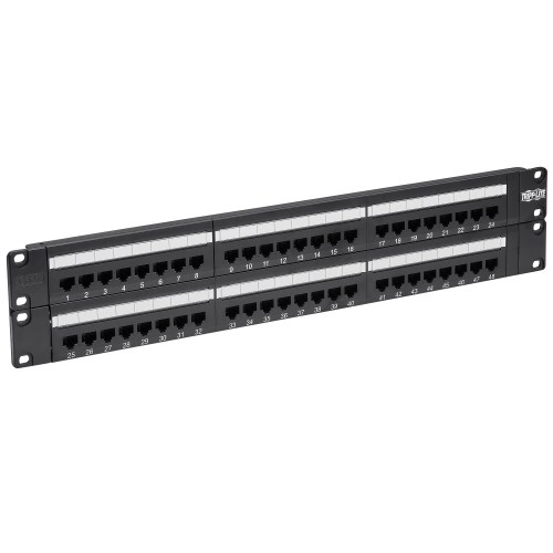
The vector stencils library ' Rack diagrams' contains 33 rack design elements for drawing the computer network server rack diagrams. 'A 19-inch rack is a standardized frame or enclosure for mounting multiple 1U patch panel, patch panel. Rack Mount Patch Panel Visio Stencil. The Xpress Fiber Management® (XFM®) 1U patch panel is a rack mountable interconnect point specifically designed to manage dense fiber applications. Based on the LGX® intermateability platform, the panel is fully compatible with AFL's XFM® Optical Cassette, Passive Optical Coupler Modules and Poli-MOD solutions.
With Microsoft Visio, you can quickly build a rack diagram from equipment shapes that conform to industry-standard measurements. The shapes are designed to fit together precisely, and their connection points make them easy to snap into place. You can also store data such as serial number and location with the equipment shapes and generate detailed reports based on that data.
What do you want to do? Create a rack diagram • On the File menu, point to New, point to Network, and then click Rack Diagram.
• From Rack-mounted Equipment, drag a Rack shape onto the drawing page. Snk Vs Capcom Svc Chaos Ps2 Download. To hide the U height, right-click the shape and then click Hide U sizes on the shortcut menu. • Find an equipment shape that you want to add to your drawing, and drag it onto the Rack shape. Connection points at the lower corners of the equipment shape are glued to the connection points on the Rack shape. When the equipment shape is correctly connected to the Rack shape, the connection points turn to a different color, indicating that they are glued. Notes: • In Visio 2007, the control handle is:. • In Visio 2016, the control handle is:.
• To store data with a shape, right-click the shape, point to Data on the shortcut menu, and then click Shape Data. • In the Shape Data dialog box, type values for the data that you want to store. Generate equipment reports • In Visio 2007, on the Data menu, click Reports. In Visio 2016, on the Review menu, click Shape Reports. • In the Reports list, click the name of the report definition that you want to use. Notes: • To modify an existing report definition before you generate a report, select the report definition, click Modify, and then follow the instructions in the Report Definition Wizard.